

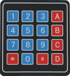
Voilà je viens de recevoir mon keypad 4x4. J'ai donc voulu faire mumuse avec, mais forcement si je viens vers vous c'est que ça ne fonctionne pas.
Le hic c'est que je souhaite simplement afficher la touche appuyé sur un LCD 16x2. Sous mikroc il y a bien un exemple. Mais le souci, c'est que je souhaite afficher sur un LCD I2C comme paulfjujo m'a déjà montrer ici.
J'ai donc repris le code LCD I2C (schema compris) a l'identique et ajouter au code les options concertants le keypad de l'exemple de mikroc. Forcement ça ne fonctionne pas.
EDIT :
Code et schéma fonctionnel après rectification.
Voici le code :
Code : Tout sélectionner
///////////////////////////////
//    name : KEYPAD LCDI2C   //
//    create : venom         //
//    date : 18/04/2019      //
//    pic : 16f887 4MHz      //
///////////////////////////////


#define _LCD_FIRST_ROW          0x80     //Move cursor to the 1st row
#define _LCD_SECOND_ROW         0xC0     //Move cursor to the 2nd row
#define _LCD_THIRD_ROW          0x94     //Move cursor to the 3rd row
#define _LCD_FOURTH_ROW         0xD4     //Move cursor to the 4th row
#define _LCD_CLEAR              0x01     //Clear display
#define _LCD_RETURN_HOME        0x02     //Return cursor to home position, returns a shifted display to
                                         //its original position. Display data RAM is unaffected.
#define _LCD_CURSOR_OFF         0x0C     //Turn off cursor
#define _LCD_UNDERLINE_ON       0x0E     //Underline cursor on
#define _LCD_BLINK_CURSOR_ON    0x0F     //Blink cursor on
#define _LCD_MOVE_CURSOR_LEFT   0x10     //Move cursor left without changing display data RAM
#define _LCD_MOVE_CURSOR_RIGHT  0x14     //Move cursor right without changing display data RAM
#define _LCD_TURN_ON            0x0C     //Turn Lcd display on
#define _LCD_TURN_OFF           0x08     //Turn Lcd display off
#define _LCD_SHIFT_LEFT         0x18     //Shift display left without changing display data RAM
#define _LCD_SHIFT_RIGHT        0x1E     //Shift display right without changing display data RAM

// LCD Definitions
#define LCD_ADDR 0x7E                    // adresse du PCF8574A = 0x7E. adresse du PCF8574 = 0x4E


unsigned short kp;

// Keypad module connections
char  keypadPort at PORTD;


// Lcd constants
char txt1[] = "Bouton presser :";
char txt2[] = "";


void I2C_LCD_Cmd(char out_char) {

    char hi_n, lo_n;
    char rs = 0x00;

    hi_n = out_char & 0xF0;
    lo_n = (out_char << 4) & 0xF0;

    I2C1_Start();
    I2C1_Is_Idle();
    I2C1_Wr(LCD_ADDR);
    I2C1_Is_Idle();
    I2C1_Wr(hi_n | rs | 0x04 | 0x08);
    I2C1_Is_Idle();
    Delay_us(50);
    I2C1_Wr(hi_n | rs | 0x00 | 0x08);
    I2C1_Is_Idle();
    Delay_us(100);
    I2C1_Wr(lo_n | rs | 0x04 | 0x08);
    I2C1_Is_Idle();
    Delay_us(50);
    I2C1_Wr(lo_n | rs | 0x00 | 0x08);
    I2C1_Is_Idle();
    I2C1_stop();

    if(out_char == 0x01)Delay_ms(2);
}

void I2C_LCD_Chr(char row, char column, char out_char) {

    char hi_n, lo_n;
    char rs = 0x01;

    switch(row){

        case 1:
        I2C_LCD_Cmd(0x80 + (column - 1));
        break;
        case 2:
        I2C_LCD_Cmd(0xC0 + (column - 1));
        break;
    };

    hi_n = out_char & 0xF0;
    lo_n = (out_char << 4) & 0xF0;

    I2C1_Start();
    I2C1_Is_Idle();
    I2C1_Wr(LCD_ADDR);
    I2C1_Is_Idle();
    I2C1_Wr(hi_n | rs | 0x04 | 0x08);
    I2C1_Is_Idle();
    Delay_us(50);
    I2C1_Wr(hi_n | rs | 0x00 | 0x08);
    I2C1_Is_Idle();
    Delay_us(100);
    I2C1_Wr(lo_n | rs | 0x04 | 0x08);
    I2C1_Is_Idle();
    Delay_us(50);
    I2C1_Wr(lo_n | rs | 0x00 | 0x08);
    I2C1_Is_Idle();
    I2C1_stop();
}

void I2C_LCD_Init() {

    char rs = 0x00;

    Delay_ms(100);                         // laisser le temps au LCD de s'alimenter correctement

    I2C1_Start();
    I2C1_Is_Idle();
    I2C1_Wr(LCD_ADDR);
    I2C1_Is_Idle();

    Delay_ms(30); //30 // laisser le temps au LCD de s'alimenter correctement

    I2C1_Wr(0x30 | rs | 0x04 | 0x08);
    I2C1_Is_Idle();
    Delay_us(50);
    I2C1_Wr(0x30 | rs | 0x00 | 0x08);
    I2C1_Is_Idle();

    Delay_ms(10); //10 // laisser le temps au LCD de s'alimenter correctement

    I2C1_Wr(0x30 | rs | 0x04 | 0x08);
    I2C1_Is_Idle();
    Delay_us(50);
    I2C1_Wr(0x30 | rs | 0x00 | 0x08);
    I2C1_Is_Idle();

    Delay_ms(10); //10 // laisser le temps au LCD de s'alimenter correctement

    I2C1_Wr(0x30 | rs | 0x04 | 0x08);
    I2C1_Is_Idle();
    Delay_us(50);
    I2C1_Wr(0x30 | rs | 0x00 | 0x08);
    I2C1_Is_Idle();

    Delay_ms(10); //10 // laisser le temps au LCD de s'alimenter correctement

    I2C1_Wr(0x20 | rs | 0x04 | 0x08);
    I2C1_Is_Idle();
    Delay_us(50);
    I2C1_Wr(0x20 | rs | 0x00 | 0x08);
    I2C1_Is_Idle();
    I2C1_Stop();

    Delay_ms(100); //100 // laisser le temps au LCD de s'alimenter correctement

    I2C_LCD_Cmd(0x28);
    I2C_LCD_Cmd(0x06);
}

void I2C_LCD_Out(char row, char col, char *text) {
    while(*text)
         I2C_LCD_Chr(row, col++, *text++);
}


void main() {
    OSCCON = 0b01101000;                   // configuration OSCCON interne 4mhz
                                           // 0b01110000 oscillateur 8 Mhz
                                           // 0b01101000 oscillateur 4 Mhz
                                           // 0b01011000 oscillateur 2 Mhz
                                           // 0b01001000 oscillateur 1 Mhz
                                           // 0b00111000 oscillateur 500 Khz
                                           // 0b00101000 oscillateur 250 Khz
                                           // 0b00011000 oscillateur 125 Khz
                                           // 0b00001000 oscillateur 31 kHz

    while(OSCCON.HTS==0);                  // boucle en attendant de voir le flag à 1


    Keypad_Init();                         // Initialize Keypad

    C1ON_bit = 0;                          // Disable comparators
    C2ON_bit = 0;

    ANSEL  = 0;                            // Configure AN pins as digital I/O
    ANSELH = 0;

    I2C1_Init(100000);                     // initialisation de l'I2C

    I2C_LCD_Init();
    I2C_LCD_Cmd(_LCD_CURSOR_OFF);
    I2C_LCD_Cmd(_LCD_CLEAR);
    I2C_Lcd_Out(1,1,txt1);                 // affiche le texte en 1ere ligne
    I2C_Lcd_Out(2,1,txt2);                 // affiche le texte en 2eme ligne

    do {
     kp = 0;                               // reset de la variable kp


     do
      kp = Keypad_Key_Click();             // Mémoriser le code clé dans la variable kp

     while (!kp);
     // Préparer la valeur de sortie, transformer la clé en sa valeur ASCII
     switch (kp) {
      case  1: kp = 49; break; // 1
      case  2: kp = 50; break; // 2
      case  3: kp = 51; break; // 3
      case  4: kp = 65; break; // A
      case  5: kp = 52; break; // 4
      case  6: kp = 53; break; // 5
      case  7: kp = 54; break; // 6
      case  8: kp = 66; break; // B
      case  9: kp = 55; break; // 7
      case 10: kp = 56; break; // 8
      case 11: kp = 57; break; // 9
      case 12: kp = 67; break; // C
      case 13: kp = 42; break; // *
      case 14: kp = 48; break; // 0
      case 15: kp = 35; break; // #
      case 16: kp = 68; break; // D

     }

    I2C_LCD_Chr(2,1,kp);                   // affiche la touche sur la 2eme ligne
    }

    while(1); {                            // boucle infini

    }
}
Ainsi qu'une photo du schéma :
Merci a tous. Je précise que pour le moment mes tests sont uniquement en simulation.
Vidéo du montage sur breadbord
@++


